
- Step 1: Preparing the case
- Step 2: Installing the CPU
- Step 3: Installing RAM
- Step 4: Installing the Motherboard
- Step 5: Making Motherboard Connections
- Step 6: Installing an SATA two drive array
- Step 7: Installing Adapters, Nvidia GeForce PCI Express
- Step 8: Finishing the hard drive array
- Step 9: Installing the DVD recorder
- Step 10: Closing up and CMOS Setup
Copyright 2018 by Morris Rosenthal
All Rights Reserve
Build Your Own PC - Step 4: Installing the Motherboard
The first step to installing our motherboard is to remove the standard I/O core shield that shipped with our case and replace it with the custom shield that matches the motherboard I/O core. Some standard I/O shields are actually stamped out of the same metal as the back of the case, as in our Chapter 5 build. This standard I/O shield is a separate piece held in place by spring force of the folded metal strips along the edges of the shield. A screwdriver serves to help compress the spring along one edge, after which the shield can be pushed down into the case.
Figure 24: Removing the standard I/O shield

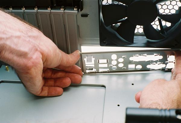
The custom I/O shield is now installed in the opening from the inside of the case. The symbols identifying the I/O ports face the outside of the case, and any grounding or positioning tabs above the port holes face the inside of the case. The two round port holes for the keyboard and the mouse go next to the power supply. The I/O shield is simply pressed into the opening, where spring force keeps it in place.
Figure 25: Installing the custom I/O shield
Some cases ship with a number of brass standoffs preinstalled in standard mounting positions, but this doesn't mean they will line up with the holes in your motherboard. Place the motherboard next to the case, and install standoffs in the predrilled holes in the case where it looks like they'll match holes in the motherboard. Count all of the installed standoffs, but do not tighten them at this point.
Figure 26: Screwing standoffs into the motherboard by hand

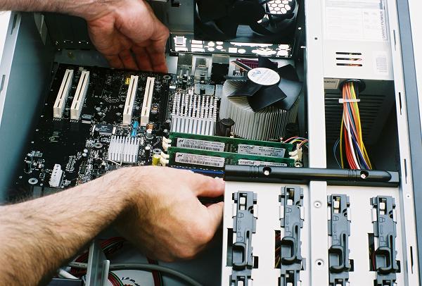
Next we test fit the motherboard in the case, lowering it down onto the standoffs with two hands and then easing towards the back of the case until the I/O core is in position through the I/O shield. To avoid dragging the motherboard on the standoffs during this operation, I usually lift a little on one of the white PCI slots and on the motherboard edge towards the front of the case. Now inspect the solder ringed holes in the motherboard and make sure there's a brass standoff under each. If you have trouble determining this, shining a flashlight through the holes or under the motherboard can help.
Figure 27: Fitting the motherboard in the case
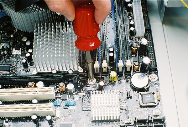
Next, remove the motherboard again, take out any standoffs that didn't align with holes, then tighten the remaining standoffs. You can use a nut driver, socket, adjustable wrench or even pliers, just make sure you don't create any brass splinters, or clean them up if you do. A fraction of a turn is all it takes to tighten a standoff. Count the standoffs, reinstall the motherboard, and install a screw in each ringed hole. If the screw count doesn't match the standoff count, you're going to have to remove the motherboard again and recount.
Figure 28: Tightening the motherboard screws
Double check that the I/O core is fully engaged through the I/O shield, and that none the metal tabs have been folded over any port openings. The I/O core of this Intel D925XCV motherboard includes all the standard I/O ports, plus a Gigabit Ethernet port, four USB 2.0 ports, a FireWire port, optical and coax S/PDIF ports. Five audio out ports are present for the integrated eight channel (7.1) sound.
Figure 29: Fully engaged I/O core

Proceed to Step 5: Making Motherboard Connections