 Build
Your Own PC
Build
Your Own PC
- Step 1: Preparing the case
- Step 2: Installing the CPU
- Step 3: Installing RAM
- Step 4: Installing the Motherboard
- Step 5: Making Motherboard Connections
- Step 6: Installing an SATA two drive array
- Step 7: Installing Adapters, Nvidia GeForce PCI Express
- Step 8: Finishing the hard drive array
- Step 9: Installing the DVD recorder
- Step 10: Closing up and CMOS Setup
Copyright 2018 by Morris Rosenthal
All Rights Reserve
Build Your Own PC - Step 1: Preparing the Case
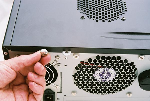
The Antec case we chose for our build was purchased from our local CompUSA store, where a variety of cases were displayed with the side panel removed to display the internal features. However, some of the nicest features are only obvious with the side panel installed, namely the thumb screws for opening the case and the combination locking/alignment tab. To the right of the thumb screw being removed in the picture is the protruding tab with a hole that can be padlocked to prevent component removal if the system is used in a public area.
Figure 1: Removing the side cover thumb screw
After removing the thumbscrews and sliding the case cover straight back using the finger groove also visible in the previous picture, we need to remove the front facade. Front facades are not all removable, you have to inspect the inside of the case along the front to see if there's an obvious attachment mechanism. In this case, the facade is locked in by a series of plastic latching tabs along both edges. Each latch is disengaged from the case by pushing it out towards the edge of the case.
Figure 2: Dissengaging a front facade latch

As each latching tab is freed, lift the facade away from the case at the bottom. Removable front facades are always lifted off from the bottom and pivot at the top, because doing it the other way would run into interference from any installed 5.25" drives. Lift the facade slowly and stop at any sign of resistance, since you've either missed the next tab, or the wires from the front facade LEDs and buttons are hung up in the case.
Figure 3: Removing the front facade

With the front facade removed, the four 5.25" bays at the top of the midtower are revealed. The Antec case uses an ingenious screwless rail system for mounting drives, with one snap-on rail used for each drive. We remove the snap-on rail which is conveniently stored on the metal bay shield, then we work the blank back and forth until the metal tongues fatigue and it breaks free. The purpose of these metal shields is to prevent radio frequency noise from escaping the case, so don't remove any more blanks than you have drives to install. After removing the shield, reinstall the front facade.
Figure 4: Breaking out the 5.25" bay shield

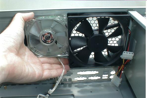
The case came with a 120 mm fan installed to exhaust hot air through the back of the case. Standard case fans are only 80 mm, and you'll often see room for two 80 mm rear exhaust fans in cases that don't employ a 120 mm fan. The following figure shows the 80 mm muffin fan we are preparing to install in the front of the case next to the 120 mm exhaust fan for comparison.
Figure 5: 80 mm fan and 120 mm fan
Fans aren't actually sold as intake fans or exhaust fans. Fans only blow in one direction so the function depends on which way you face the fan when you install it. Most cases either come with a front intake fan installed or with some form of snap-in fan mounting. This case provided a snap-in fan enclosure for the front that doubles as a guide for long adapter cards. We install the fan in the enclosure, making sure the label will face into the case.
Figure 6: Installing the front intake fan

The intake fan enclosure pivots on the bottom edge and snaps into the place at the top. Note that the label on the fan motor is facing the inside of the case, so it will function as an intake fan. Also note that we routed the wires for the fan through the center of the enclosure so they won't get pinched. Including the fan of the CPU heatsink, the fan on video adapter, and the power supply fan, we end up with a total of five cooling fans in this build.
Figure 7: Mounting the intake fan enclosure

The final step in preparing our Antec case for building is to remove the plastic accessory holder that covers the adapter slots. For an example of a locking rail used to secure the adapters, see our Athlon 64 build in Chapter 5. The plastic accessory holder doesn't contribute to securing the adapters, but when we reinstall it Figure 53, you'll see the storage compartment in the holder that's accessible from the back of the case. The open space created above the slots makes it easier to install the adapters..
Figure 8: Removing the adapter slots cover

Proceed to Step 2: Installing the CPU