
- Step 1: Preparing the case
- Step 2: Installing the CPU
- Step 3: Installing RAM
- Step 4: Installing the Motherboard
- Step 5: Making Motherboard Connections
- Step 6: Installing an SATA two drive array
- Step 7: Installing Adapters, Nvidia GeForce PCI Express
- Step 8: Finishing the hard drive array
- Step 9: Installing the DVD recorder
- Step 10: Closing up and CMOS Setup
Copyright 2018 by Morris Rosenthal
All Rights Reserve
Build Your Own PC - Step 2: Installing the CPU
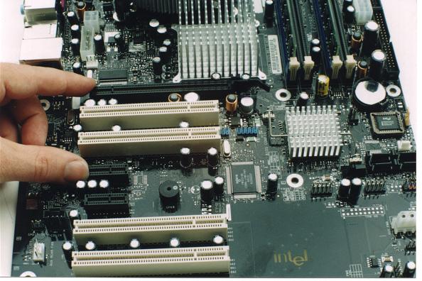
The motherboard and CPU used in the 4th edition of Build Your Own PC are typical of standard ATX parts, even though multi-core CPU's like Core i3 and Core i5 and Core i7 now rule the Intel roost. The CPU sockets are bigger than the Socket 775 used in this build, but all are LGA sockets, and the building techniques are identical. The motherboard for our Pentium 4 560 build is an Intel D925XCV. This was one of the first motherboards to support the LGA (Land Grid Array) version of the Pentium 4, in addition to introducing PCI Express 16X as a replacement for the long-standard AGP video. We install both the CPU and the memory before mounting the motherboard in the case. The PCI Express slots are black, so though don't show up as clearly as the white PCI conventional slots in the figure, but the forefinger in the picture is pointing out the sole PCI Express 16X slot, and the thumb is on one of the two PCI Express 1X slots.
Figure 9: PCI Express slots
The first step to installing the LGA version of the Pentium 4 is to remove the protective cover from the CPU Socket. Since Socket 775 consists of pins, rather than holes, it could be irreparably damaged if something bashed or bent in a number of pins. The plastic cover is picked up on the end with "remove" stamped on it, then lifted away from the socket.
Figure 10: Removing the protective cover from Socket 755

Next we lift the load lever by pulling it slightly away from the socket wall to disengage from the plastic ear, then lift it well past the vertical and let it down at the end of its travel. The load lever is several times beefier than locking levers on recent CPU sockets, because it actually compresses the spring steel of the load plate after the CPU is installed.
Figure 11: Lifting the locking lever

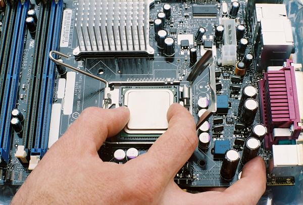
The load plate is unique to the LGA CPU, which is pressed down on the contact legs in the socket. Previous PGA (Pin Grid Array) designs have the CPU pins seat in the socket holes, and the locking lever only functioned to lock the pins into place. The load plate is lifted up, a little past the vertical, where it stops and should remain in place.
Figure 12: Lifting the CPU retention bracket

There's a little gold triangle on one corner of the CPU package that matches the pin 1 corner of the socket. The CPU is aligned by two keys in the socket and two notches towards one side of the CPU package, so it can only sit flush in the socket when inserted properly. Make sure you have a good hold on the CPU as you lower into the socket, because the CPU could damage the landing pins if it gets dropped on a steep angle.
Figure 13: Seating the Pentium 4 on the landing pins
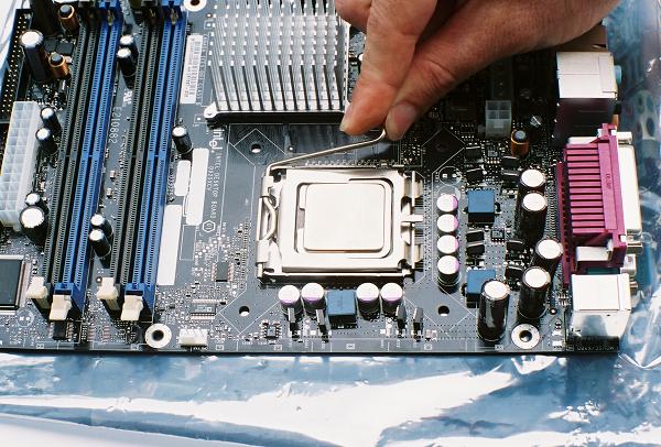
Once our 3.6 GHz Pentium 4 is sitting level in the socket and you can plainly see the two notches in the CPU package are filled with the socket keys, lower the load plate until it sits loosely on the top of the CPU package. Now bring the load lever back up through the vertical and lower it until you can snap it under the stub holder on the side of the socket. Lowering the lever takes a bit of force because you are compressing the load plate, which in turn forces the CPU down tightly on the landing pins.
Figure 14: Locking the Pentium 4 into place
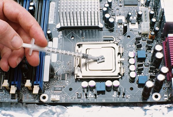
Next we apply the thermal compound supplied with our Intel heatsink to the CPU. The instructions that came with the heatsink actually suggested we "mound" the thermal compound on the center of the CPU, which is what we did. Note this is in sharp contrast with many older types of heatsink/socket combinations that require just a drop of thermal grease. The small holes for the heatsink fasteners are visible less than an inch from each corner of the socket.
Figure 15: Applying thermal compound to the CPU
The evaluation heatsink assembly Intel supplied shipped with a protective plastic film over the copper core of the heatsink. The fan wiring needs to be routed right through the heatsink fins (the wires are protected by a high temperature insulation) and pulled out the bottom, so it doesn't interfere with the fan. The left hand in the picture is holding the wires in place as the right hand peels off the plastic film.
Figure 16: Preparing the heatsink for installation

As the heatsink is lowered over the CPU, make sure the wires don't get pinched underneath. The heatsink should be lowered straight down on the CPU, but we're showing it on a tilt here so not to completely obscure the socket. There is a white snap-in fastener on each corner of the heatsink, and four matching holes in the motherboard.
Figure 17: Heatsink shown over Socket 755

Once the snap-in fasteners on each corner of the heatsink are matched with the holes in the motherboard, simply push down on each black fastener cap until it clicks into place. The only trick is to lift up the motherboard a little so there's room for the connector to go through the hole. Flip the motherboard over when you're done and make sure the fasteners are fully engaged.
Figure 18: Securing the heatsink fasteners

As soon as the heatsink is properly installed, connect the power for the heatsink fan to the designated fan connector on the motherboard. The connector is usually located right of the edge of the motherboard next to the CPU socket, but make sure the printing on the motherboard or the accompanying manual identifies it as the CPU fan point. This allows the BIOS to monitor the health of the fan and control its activity in power management modes.
Figure 19: Connecting the heatsink fan

Proceed to Step 3: Installing RAM