One day, after getting irritated by highway vibrations, it occurred to me
to shake the tire while it was still on the ground. It moved some, a bad
sign in itself, and there was a nasty clicking noise that testified to a
loose joint. The question was whether the looseness was in the lower ball
joint, which attaches the wheel assembly to the lower control arm, or one
of the tie rod joints, that tie the steering knuckle to the rack and provide
for steering. So I jacked up the front end of the car, and shook the wheel
while it was up in the air. There was almost no movement or noise when I
shook it with a hand at the top and the bottom on the tire, but plenty of
movement and noise when I shook it with my hands to the left and right, just
like on the ground. That told me that the looseness was in the tie rod, but
not whether it was the inner tie rod joint or the tie rod end, also called
the outer tie rod joint. I took the video at the right, because I just couldn't
see what was happening when I had to shake the tire at the same time, plus
I though it made for a neat diagnostic aid.
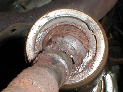
So, unfortunately, the problem turned out to be the inner tie rod ball joint,
where the housing for the rusty joint shown is attached to the piston that
comes out of the rack and steers the car. I've obviously removed the boot
for the picture shown to the left, but it's a good time to point out that
there's a breather tube running from the boot on one side of the rack to
the boot on the other side of the rack. It's important, because it allows
the boots to expand and contract (one is always stretching if the other is
compressing) without collapsing or needing to suck air from the outside world.
The seals on the rack that keep the hydraulic fluid for power steering from
squirting out, wouldn't last long if there was grit getting rubbed against
them all the time, or if the car was parked a long period with the wheel
cranked over and the piston rusted.
The first step in replacing the inner tie rod is to remove the tie rod end.
It's basically a three step process, where you start by loosening the jam
nut that's used to set the alignment (toe-in or toe-out). That jam nut determines
how far up the inner tie rod the tie rod end is fixed. The tie rod end is
hollow and threaded, so it can be screwed on or off the inner tie rod. Any
procedure for removing a tie rod will start by telling you to count the turns
you unscrew the tie rod end, something that I didn't do, and I'll save the
explanation for the end:-) After you loosen the jam nut, you remove the cotter
pin from the post on the outer tie rod ball joint, and unscrew the nut that
holds the ball joint into the tapered fitting on the steering knuckle (video
to right). After you pop the outer tie end free of the steering knuckle,
you can unscrew the tie rod end. from the inner tie rod, but you need to
grip it with something. Inner tie rods normally have some flat surfaces or
a splined surface for grabbing with pliers. In this case, I needed two pairs
of visegrips and a clamp to hold the visegrips on the inner tie rod from
moving in order to get the outer tie rod end broken free and turning easy.
That video is below.
I happen to own the shop manuals for my Dodge Omni, so I was able to study
the procedure for replacing the inner tie rod in detail. I didn't follow
it for a couple reason. First, they show my type of power steering rack (Saginaw
vs TRW) needs to be removed from the car to change the inner tie rod. That's
a lot of extra work, not to mention the fact I buried one of the
crossmember bolts in my unibody and flooring repair!
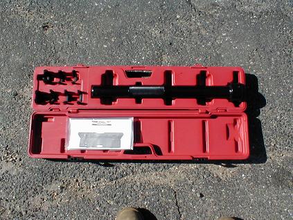
So I went with an inner tie rod removal kit from Harbor Freight, manufactured
by U.S. General (in Taiwan). The tool is very simple, basically a large steel
tub with a snap in opening for a large crows foot insert on one end and a
1/2" socket drive on the other end. The kit is shown in the photo to the
lower left (which I need to replace), and a video of the procedure is shown
below. The kit wasn't quite right for my car, I had to use an oversized crows
foot and the ball joint housing on the inner tie rod was too long, so the
flats on the housing were barely held with the crows foot positioned by hand
at the very end of the tool. But I got it out.
I know the details in the videos get lost from time to time, so here's a
snap shop of installing the inner tie rod, screwing it over the end of the
shaft by hand. If you look at the hose clamp I put in place to hold the boot,
which isn't shown here, you can see that breather tube I was talking about
above below the screw on the clamp and closer to the shaft. You also get
a pretty good look at the flat surface that the crows foot Harbor Freight
tool will hold onto to tighten it. It needs to get torqued to 70 foot-pounds.
I'll admit I went with loctite on both the shaft and the thread in the housing
and over-torqued it a little by feel without a torque wrench. I was fed up
with the instructions by this point because they kept on going on about staking
the inner tie rod to the rack for the Saginaw. It wouldn't have been possible
with my replacement tie rod unless I drilled a hole!
The inner tie rod I removed wasn't staked (never would have got it out
otherwise), and neither of the replacement inner tie rods sold by NAPA (TRW
or Saginaw types) had holes for staking. The TRW one had a set screw, which
comes close to staking but was the opposite of what the shop manual reported.
It's easy to tell the Saginaw from the TRW because the Saginaw has a machined
cylinder that slides over the piston end coming out of the rack, the TRW
doesn't. In the video to the left, I'm showing how the inner tie rod is installed
by hand, just screwing it onto the end. The video below shows the U.S. General
inner tie rod tool back in action to tighten up the inner tie rod. All that
remains is to reinstall the boot, and the outer tie rod. But what about the
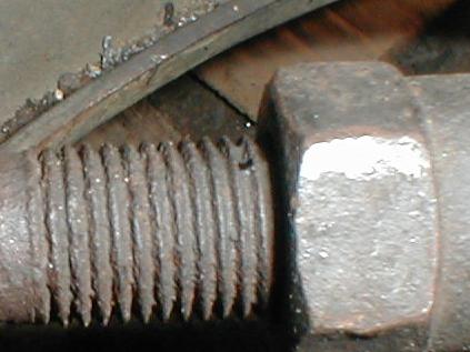
alignment? When I started the job, I took a photograph of the tie rod end
position on the inner tie rod, because I don't trust myself counting and
writing down the number fast enough not to forget it. That photo is shown
at the bottom left. I make it 12 threads to the nut. So with the old inner
tie rod in hand, I put the nut in the right place and counted threads out
to the end, which came to 24, and that's how far I screwed on the old tie
rod end. The threaded length on a replacement inner rod may not be the same
as the old rod, so you have to count from the end, not the middle.