While the videos are a lot of fun, I think that photographs do a much better
job of showing what's going on. So backing up a few steps on fabricating
a new subframe to repair the unibody, I'll show some of the basic approaches
I'm using. First, any time you don't understand precisely why something holds
together, it's a good idea to overbuild it, to make it much stronger than
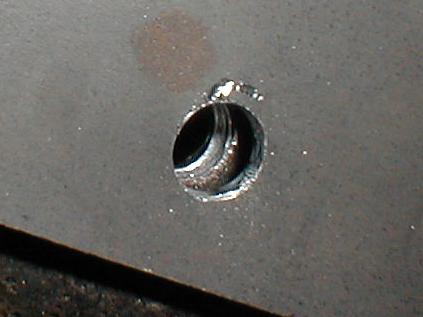
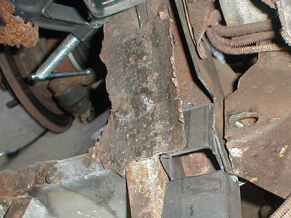
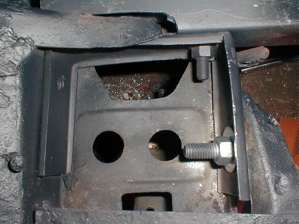
it needs to be. So wherever I can, I try to sandwich old bits of existing
subframe steel with new steel. The photo to the right shows that pretty clearly,
you can see the new steel on both side of the original steel right through
the hole. Ironically, the "original steel" seen isn't original either, it's
a replacement angle iron that was welded in place some years ago. The hole
shown was for a 5/16" bolt, which I'm using for most of the spot-weld
applications. I went to 7/16"s for the serious junctions that keep a lot
held together..
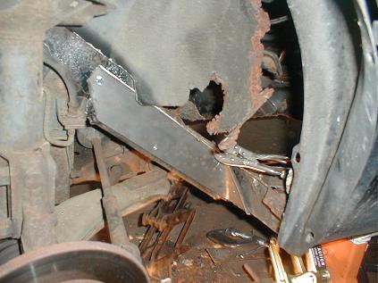
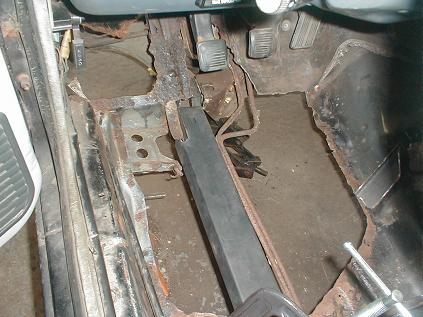
The hole you're looking at above is in the middle of the piece shown to the
left, which rides right up the subframe to stop right before the shock tower.
The subframe around and forward of the shock tower is in pretty decent shape,
probably do to the way the salt water comes off the tires near the bottom
of the wheel wells on our New England road. For scale, those are the baby
visegrips holding it clamped up. I left a small lip on the piece in hopes
it would give it a bit of extra strength, though that's probably nuts. I
also left it long so I could bend the end to fit the junction of the stubframe
with the subframe rail, and I'll bolt that through to a new piece of steel
on the other side before I'm done. In blind locations, I used for #14 sheet
metal screws, but after breaking my 3/16"s drill bit and subsequently breaking
the head of a #14 screw with my 1/4 inch ratchet (one handed) trying to force
it through a smaller hole, I switched to all bolts.
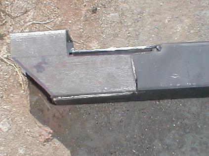
The photo on the right shows one of my compound fabrications, where I'm trying
to get the most strength I can from the tubing while getting the geometry
I need. That involves a lot of sawing, since I only have the once size of
steel tubing to work with. In this case, I was very happy with the result
because I was able to get the height perfect with a whole piece of tube turned
on its side, but I had to cut the 3" dimension down to a little under 2"
for most of the length to get it inside the longer piece of tubing that's
replacing the subframe under the driver side floor. I put it together with
three bolts, all through the outer surfaces that won't get in the way of
construction. I'm pretty unhappy with the lock washers I've been using, so
I simply sprayed the bolts with primer after snugging up the nuts - hopefully
the dried paint will act like lock-tight. (Update on spray paint as loctite.
Doesn't work for beans, no wonder there's a special purpose product:-)
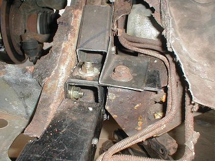
To the left you see the construction in place, along with a new piece of
steel patching subframe heading up towards the shock tower on the inside.
There's a bit of optical illusion from the camera angle, both the compound
construction and the steel side patch are on the same level as the top of
the crossmember that ties the whole front end together. If you look carefully
at the top of the photo, just under the clutch pedal which is held down by
the C-clamp, you can see the end of the homemade angle iron heading up the
subframe along the top surface of the old rail. I wish I'd made it 4" longer,
but at the time, I was trying to keep it out of the way of an insert for
the lower part which I abandoned as a stupid idea.
The picture to the right shows the long part of the compound piece stretching
back to the center of the passenger cabin, on which the front seats mount.
I think I'll continue with this page of stills until I have the front subframe
all bolted together. I bought some grade 8 steel bolts today, the 7/16" diameter
1" long bolts along with a nut and two flat washes each cost me $4 at the
local hardware store. But I wanted to use the grade 8 for the two busy
connections I made, each of which holds four layers of the 1/12" steel together,
or a 1/3" of steel when all is said and done.
The picture to the left shows the final build-up of the subframe using four
more small pieces of steel not shown in the previous picture. At the bottom
of the stack under the vertical bolts, my new 7/16" and the original 1/2"
in the crossmember, is an "L" shaped piece that curls over the small standing
section of 3" tubing and continues down along the side of it, along the inner
surface of the original subframe. Above that is a flat piece that runs between
the two bolts which I used as a template for the more complicated curved
piece, and then added to the stack. At the top of the stack is a triangular
section of tubing that ties the crossmember to two of our new pieces of steel.
First the "L" tubing section that goes under the original subframe (bolted
twice from the bottom) and catches the single bolt through out triangular
section. Second, the upside-down "U" section of tubing.
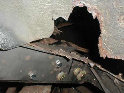
From the outside, it looks like a maniac stuffed five bolts through a flat
piece of steel for no reason. The four bolts to the right all go through
the steel pieces just shown above. The lowest bolt, a 7/16" grade 8, goes
through our new outer piece, barely catches the old welded repair angle at
the end, and then goes through the flat "L" at the bottom of our stack, and
finally the upright section of the 3" tube that brought it to level. The
3/8" grade 8 bolt next to it goes through the same pieces, but it catches
the original subframe that the angle repair was welded to. The next 3/8"
grade 8 goes through the out piece, the welded angle, and the inverted "U"
piece, and 5/16 grade 3 just above it goes through four piece of steel, the
outer piece, the original subframe, the faux angle that runs inside all the
way to the top of the shock tower, and our inverted "U". Wish I'd bought
grade 5 for everything. Below is the reinforcement I added to the stub frame
(left bolt not installed yet) which also ties our brand new subframe member
directly to the rail frame by way of the extension.
I'm closing this section of the repair with a couple videos showing the final
assembly, just in case you're wondering how the inside parts bolt together.
On of the interesting outcomes is when I ran down the big 1/2" nut on the
crossmember bolt, it lifted the crossmember a fraction of an inch off its
jack, just enough that the jack can move loose. My height adjustment for
the crossmember was nothing but a guess from the start since it was no longer
attached to anything by the time I cleared out all the rusty bits, so it
will be interesting to see if the alignment is now funky on the driver side.
Whatever the impact on driveability, I saw I took the fact that my repair
pieces of steel could lift up the crossmember without making any popping
or groaning sounds as a vote of confidence in its solidity.