
- Step 1: Preparing the case
- Step 2: Installing the CPU
- Step 3: Installing RAM
- Step 4: Installing the Motherboard
- Step 5: Making Motherboard Connections
- Step 6: Installing an SATA two drive array
- Step 7: Installing Adapters, Nvidia GeForce PCI Express
- Step 8: Finishing the hard drive array
- Step 9: Installing the DVD recorder
- Step 10: Closing up and CMOS Setup
Copyright 2018 by Morris Rosenthal
All Rights Reserve
Build Your Own PC - Step 5: Making Motherboard Connections
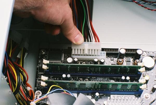
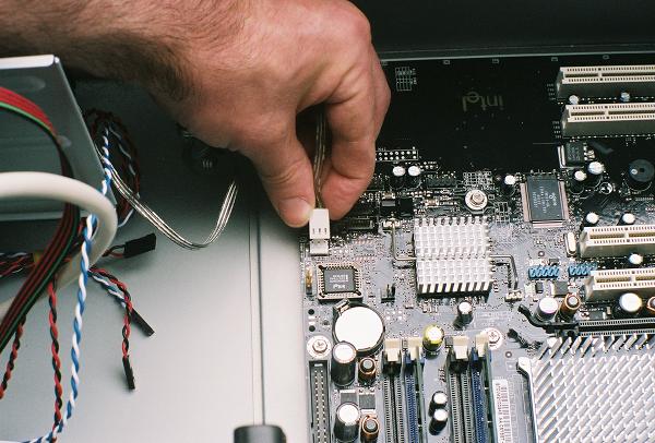
The most important step in making motherboard connections is to consult the manual that shipped with the motherboard. There are two options for powering this motherboard, one uses the standard ATX 20 wire connector, the other uses the 24 wire ATXe connector borrowed from the world of PC servers. The 24 wire receptacle on this particular Intel motherboard accepts the 20 pin connector, and it's keyed so it can only be inserted in the proper location, to one end of the receptacle.
Figure 30: Inserting the 20 wire ATX power
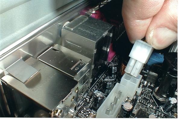
In addition to the standard 20 wire ATX power connector, this style motherboard also requires an additional 12 V connection. This is implemented as a square four wire connector that is normally located near the CPU. The connector is keyed so that it can only be inserted in the proper orientation.
Figure 31: Making the 12 V power connection
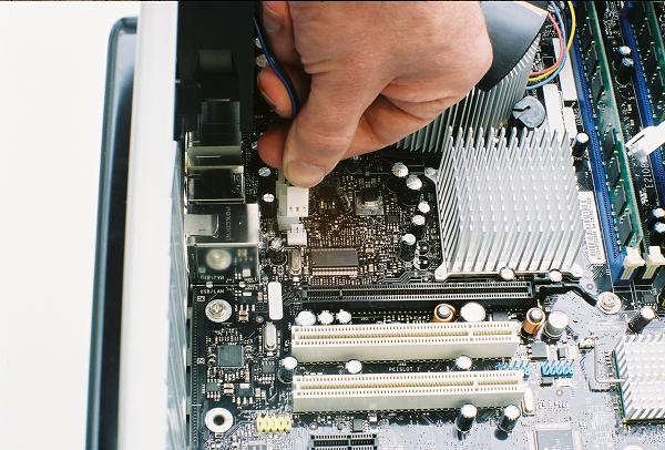
Finally, we need to do a "make up" connection, to compensate for the fact that we used a 20 wire instead of a 24 wire connector for the main motherboard power. You can buy an adapter that turns a 20 wire connector into a 24 wire connector, but if the power supply circuit doesn't provide sufficient power, it won't help. The motherboard provides an extra receptacle for a 1x4 power supply lead, which is located right next to the 12 V connector on this motherboard.
Figure 32: Installing the alternate 1x4 power connector
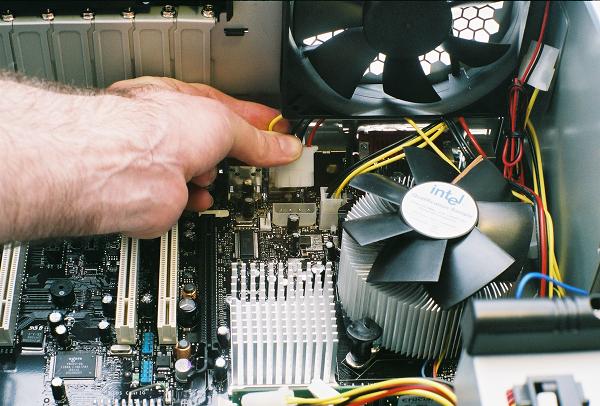
Some power supplies can vary the fan speed for enhanced cooling or decrease the speed for quiet operation. In order for the BIOS to monitor the fan speed, the power supply must have a external fan connector that can be attached to the motherboard. Since this connection is for information only, the fan doesn't draw power from the connector and it may only use one wire. This can be attached to the auxiliary or back fan connection point.
Figure 33: Attaching the power supply fan monitoring lead
The large 120 mm exhaust fan that came preinstalled in our Antec case is powered by a 1x4 connector from the power supply. Since we already brought a power supply lead to the back of the case for the auxiliary power, the second connector on the lead makes a convenient power point for the fan.
Figure 34: Providing power to the rear exhaust fan

With such a large number of power supply leads routed between the rear exhaust fan and the CPU heatsink and fan, it's necessary to secure them out of the way where they won't interfere with the fans or be in danger of insulator degradation due to contact with heatsink fins. We bundle all the loose leads together and cable tie them to the exhaust fan frame.
Figure 35: Bundling the power supply leads

The power lead for the front intake fan attaches to the front fan point on the motherboard. The 80 mm fan was equipped with a 1x4 adapter for direct connection to the power supply if a motherboard connection point wasn't available, but in this case, we're more likely to run out of power supply leads than motherboard fan connectors.
Figure 36: Attaching the power for the intake fan
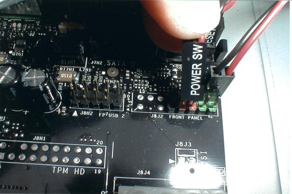
The most important connection from the front panel to the motherboard is the power switch, without which the PC can't be turned on. Depending on the motherboard and the case manufacturer, some of the front panel leads may be color coded, or even bundled into semi-standard block connectors. The functions of the front panel leads are printed right on the connectors, but the motherboard labeling may be cryptic or even absent, so have the manual at hand, or print the necessary pages if the manual only exists as a PDF on the driver CD.
Figure 37: Connecting the front panel power switch
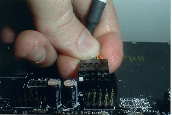
Front panel LED leads installed backwards won't operate, but the won't do any harm, while switches will work as long as they go on the correct two posts. Most new cases feature front panel USB and audio ports, and in this instance, the connector for the front two USB ports is integrated into a single cable and keyed to be installed in the proper orientation.
Figure 38: Connecting the front panel USB ports
Proceed to Step 6: Installing an SATA two drive array